I have worked as a researcher for the Harvard Microrobotics Laboratory under Dr. Robert Wood since February 2024. I spent Summer 2024 pioneering fluidic circuitry and rigid components for self-folding complex origami-inspired structures. Namely, I developed a Frog (Video 1), Chrysanthemum (Video 2), Amaryllis (Video 3), and a Tulip (Video 4).
Publication:
E. Langenbrunner, J. El-Rayess, M. A., Yuen, R.J. Wood, ”Design study of low-profile fluidic actuators for Origami-Inspired folding structure”, In preparation
Video 3

Image 1

Image 4

Image 7
Video 2
Video 4
The actuator circuits were made using a silicon molding process and 3D printed molds created in SolidWorks. There is a top mold (Tulip example: Image 2) that fits into the bottom mold (Tulip example: Image 1) in order to create pockets in the silicon when it cures. This allows the circuits to have dual-sided actuation (Images 4 & 5) once they are integrated into the rigid components (Tulip example: Images 3 & 6). Throughout the circuit development process, I experimented with silicons of varying firmness (Soft: Image 4; Hard: Image 5), different aspect ratios, thicknesses, combinations of series and parallel circuits, etc. To manufacture the silicon circuits, I used the Spin Coater, Vacuum, and 3D Printer.

Image 2

Image 5
I used the silicon circuits to actuate the rigid components (Image 8) I made from applying a 2D heat bonding layered manufacturing process. The structures were layered (from top to bottom) with cardstock, wax adhesive, Polyethylene terephthalate (PET), wax adhesive, and then cardstock again. These layers allowed the rigid forms to maintain their structural integrity while being able to fold where the flexible PET was exposed, creating a hinge. After modeling the geometry of the layers in AutoCAD, I laser cut the wax adhesive and cardstock together and the PET separately. Next, I arranged the cuts on top of one another using a 3D printed guide with dowels (Image 7) and then heat bonded the layers. In order to formalize my process and results, I documented a knowledge base for each origami-inspired structure including bending angles, stiffness effects, dimensions, and common difficulties for future implementations.
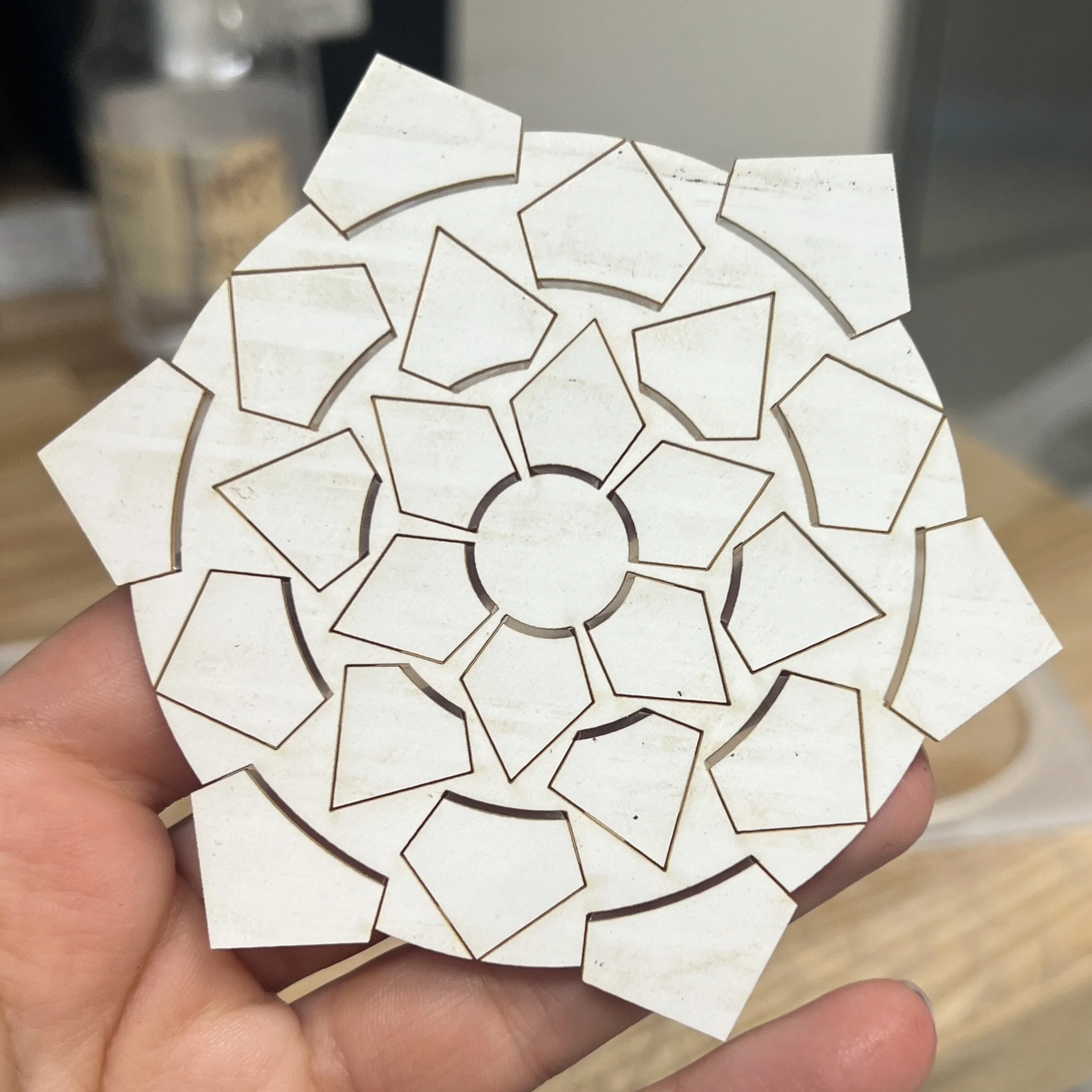
Image 9
Image 10
Image 11
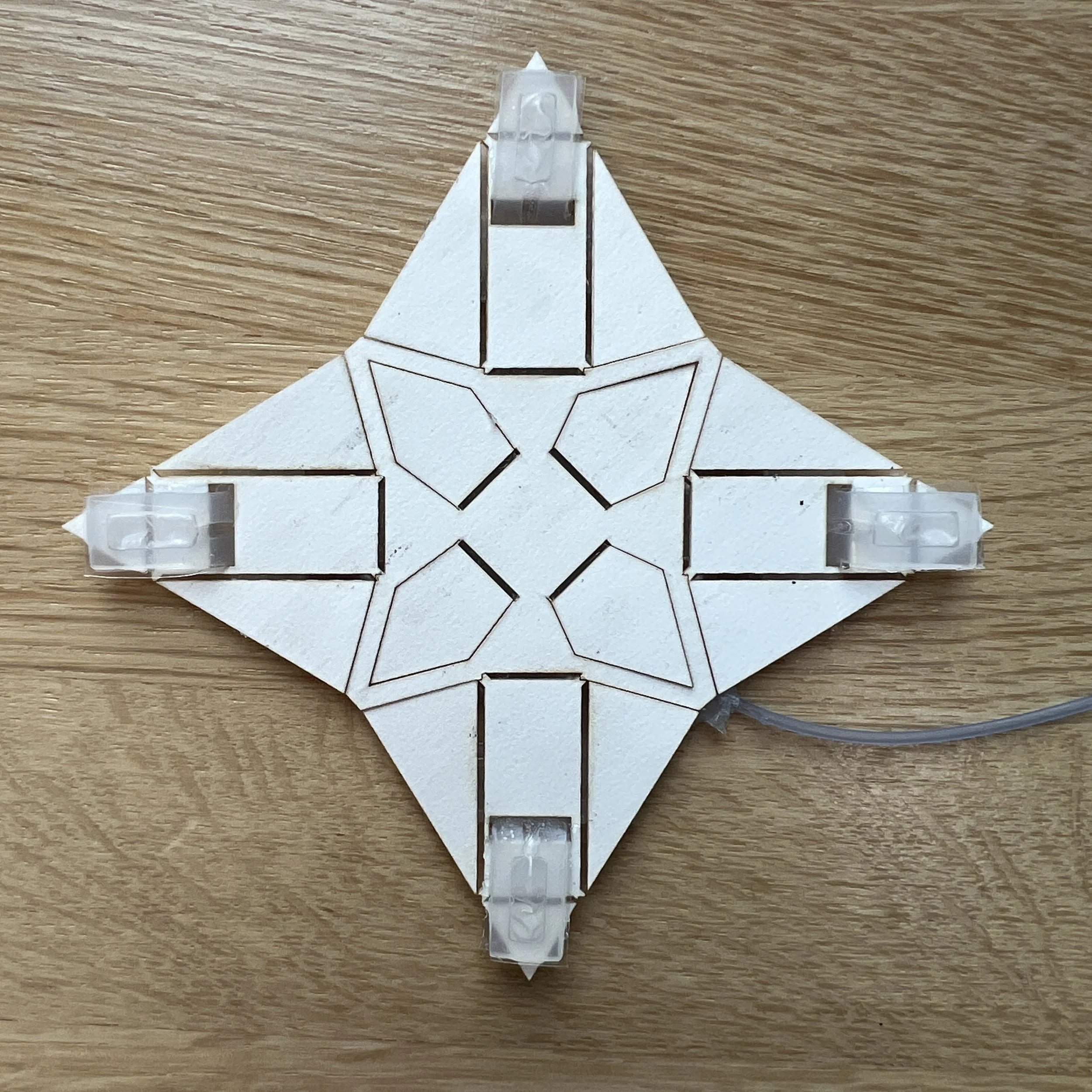
Image 3
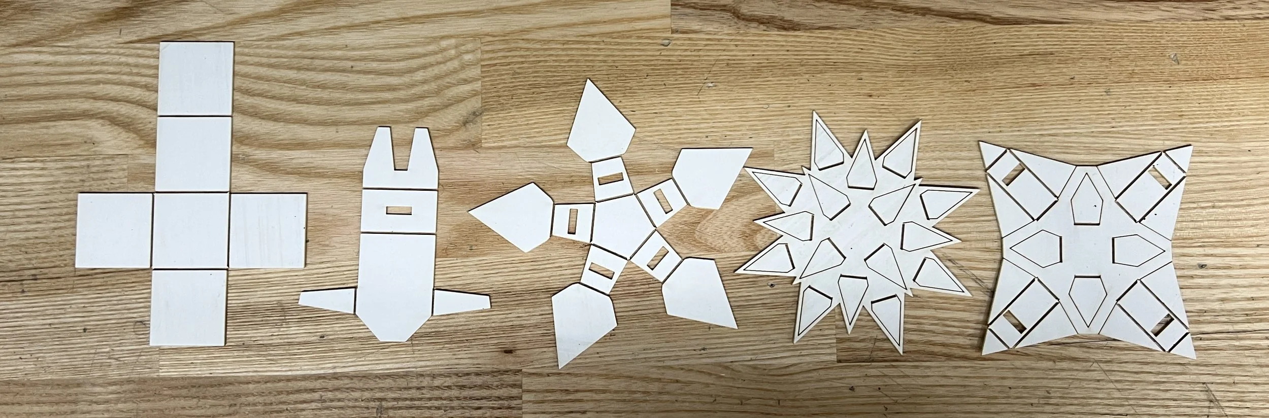
Image 8
Aside from the physical research I conducted, the majority of the process involved rapidly prototyping various origami shapes and mapping out how they would actuate. For example, I would actually make the origami (Image 11) before trying to turn it into a singular folding piece. Next, I would make multiple paper prototypes of of the piece (Tulip example: Image 10). Finally, I would start realizing my designs with the process described above to determine whether they seemed viable. For example, one of my designs that didn’t pass the final testing stage was the Lavender-inspired structure (Image 12). Even if some designs didn’t work well when produced for the first time, like in the case of the original Chrysanthemum (Image 9), after iterating upon the design, they would turn out beautiful!
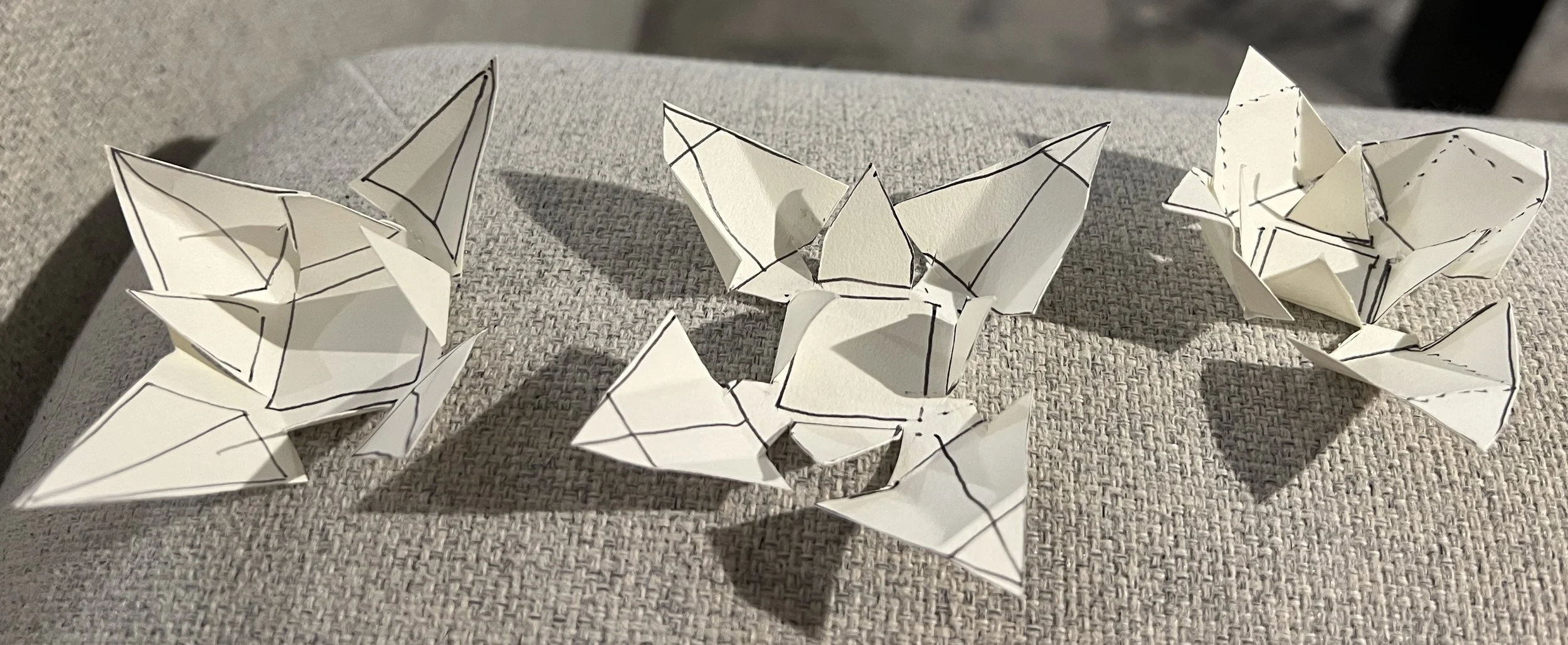
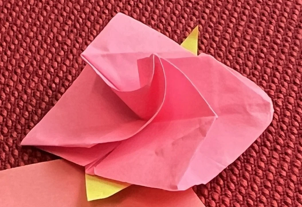
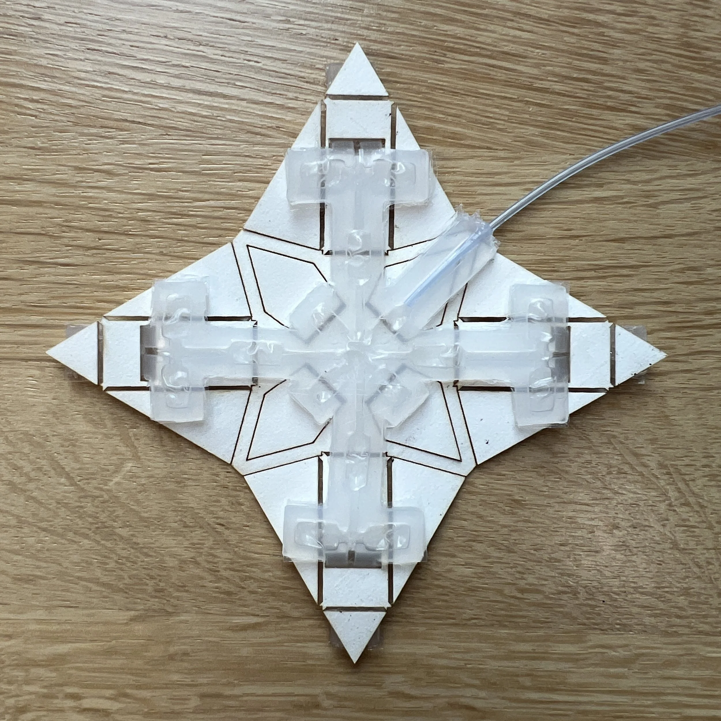
Image 6
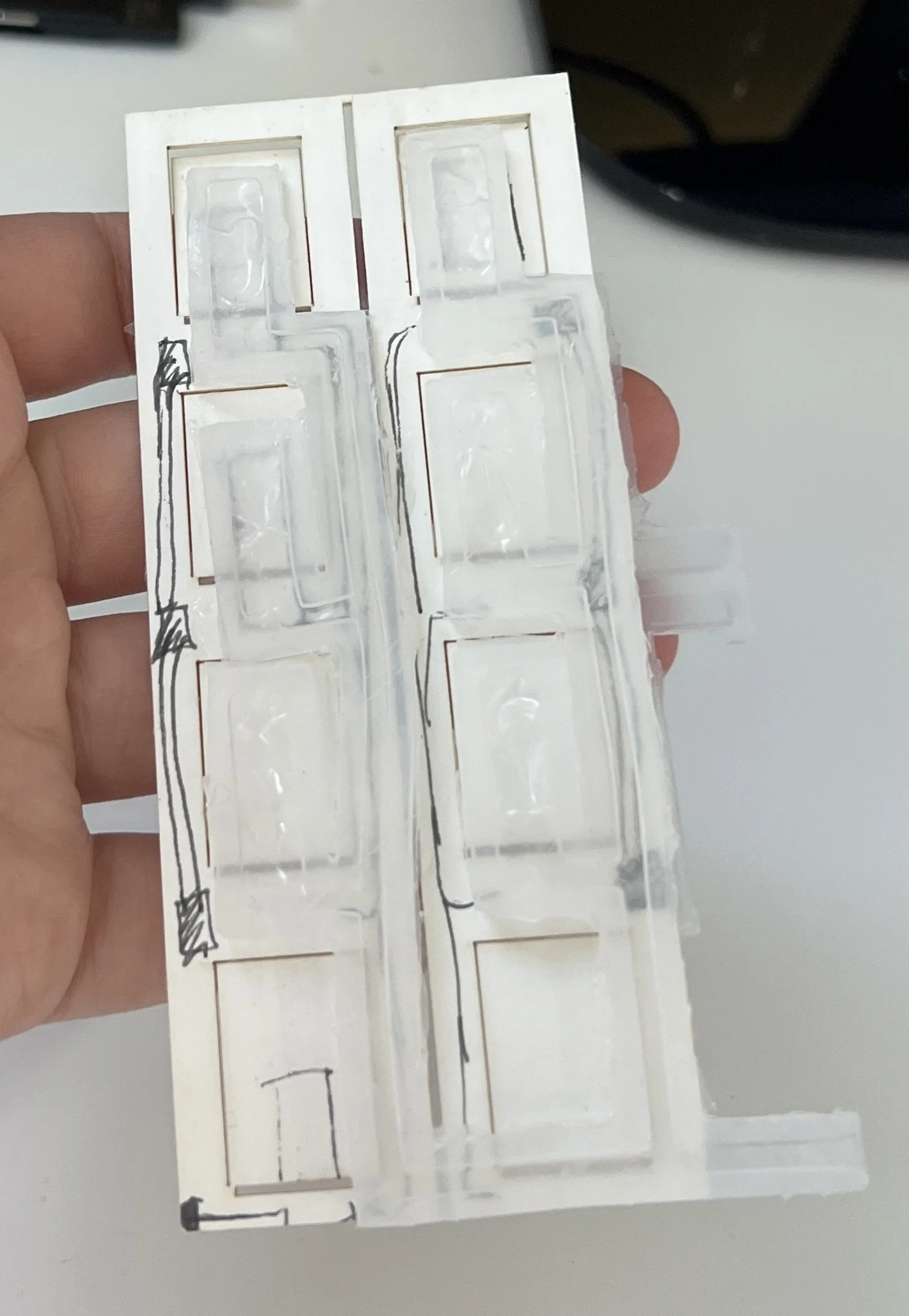
Image 12
Video 1